Mini PET build and review
For Christmas I was bought a mini-PET designed by tynemouth software and currently being sold by The future was 8 bit, I finally got around to building it over the past few days.
Rod at TFW8b often packs in a couple of surprise items so in the kit I got was a switch for the PSU cable, a PET mouse mat with a BASIC ready prompt and a pen so I’m wondering what I’ll get with the Minstrel 3/4 I’ve ordered. Anyway onto the review and build notes.
Kit contents
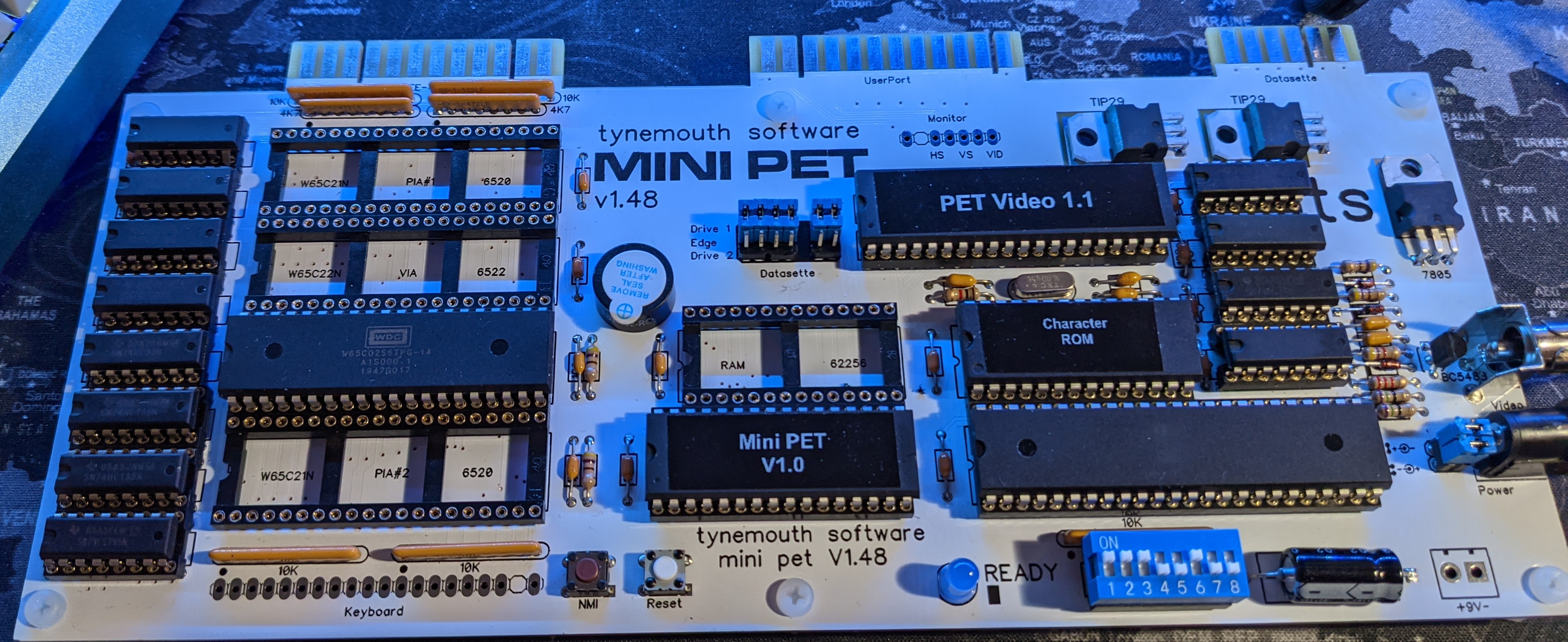
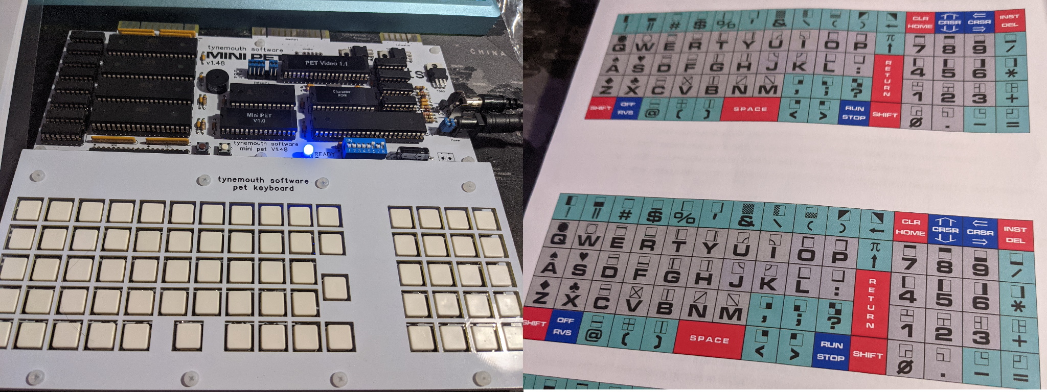
The kit comes in a stout outer wrapping box with the individual components in cushioned jiffy bags (I didn’t think to take photos). The keyboard is in one bag with the main mini-PET board in another, in my case I’ve been bought the “deluxe” chiclet key board and the optional SD2PET so I can get up and running quickly.
The main board has the IC sockets inserted in place with the semi-conductor components placed into anti-static mat in the correct order for inserting into the PCB, the discrete components (capacitors, resistors, sockets, jumpers etc) are in a separate plastic bag along with the stand offs for the board. The keyboard comes with the switches already in place and a couple of bags containing the two part key caps. Four sets of legends to cut out and fit are on the back page of the manual.
The PCBs seem to be high quality to me and I didn’t have any problems with them. The instructions are a little bit light weight for an absolute beginner, there isn’t really a parts identification guide i.e. there is an assumption you know what a diode looks like vs a capacitor, but given the target market I don’t feel this is a huge problem. Thankfully for the resistors the colours are shown in the manual which saves me having to look them up (I don’t do enough electronics these days to remember resistor colour codes).
Building the kit
I followed the recommended sequence for building the kit in the manual which is the usual sequence of starting with the lowest height components then working up. The sockets that come for the ICs are turned pin so better than a cheap dual leaf design. The only socket I probably wouldn’t fit is the one for the DIP switch as the switch is a little bit loose in that socket.
The manual covers building the board in a couple of pages but is clear enough, there is a full page component layout diagram but it would have been helpful to have numbered the semi-conductors and resistor packs when I was debugging the board later on. The circuit is documented with small relevant portions of the circuit diagram with explanatory text next to the circuit, personally I would have preferred a full circuit diagram (but that probably would need some A3 diagrams) and a PCB layout showing tracks but a multimeter gets you most of the way there.
The keyboard goes together fairly easily, although I’d check that all of the switches are pushed in firmly before soldering (I have a couple that are a fraction of a millimetre too high), once that is done it’s a case of cutting out the legends for the keys and putting them into the key caps. I made the mistake of putting the keyboard to main PCB connector on the wrong side of the PCB but to be honest I’m not really all that bothered.
This is a nice kit and the chiclet keyboard is a nice cost compromise at this level, I am going to buy the perspex case from RC2014 as I think you can bend the keyboard connector if you’re not careful when picking up the two boards once they’ve been joined together.
First power on
After inserting all the chips into the board it was time to double check the power connector option is set correctly and attach the board to a screen. I have a small 8” 4:3 ratio LCD (bought from Amazon) screen that I’ve recently bought, it claims a 1024x768 resolution and comes with a VGA cable. It seems to support both PAL and NTSC composite video (at least in monochrome from my quick test) these monitors are also available from AliExpress typical phrases to search for are “CCTV” and “Reversing camera” which throws up a few options.
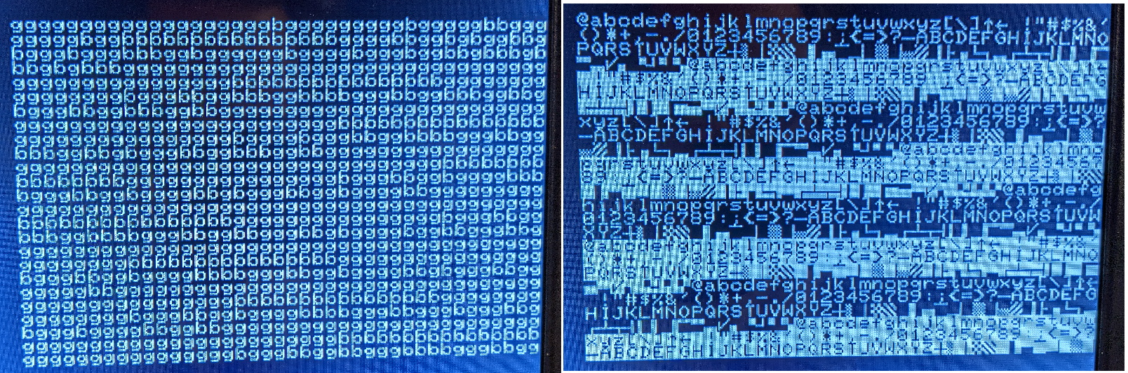
Sadly at this point I got some beeps and a video frame full of random characters. I knew there were some diagnostics in the ROM so I set the dip switches to the PET test ROM and got these two displays alternating.
Mini PET screen displaying RAM test
While this might not look too much like good news I was pretty darned happy at this point, while I’m no PET expert I can see what looks at first glance like a full character set repeated and a ram test which has some faults probably in particular rows. This means that the processor is executing code and the video circuitry is working, so it’s highly likely I have a bad joint somewhere but the board is mostly working.
It felt like time to go and have a quick look through the circuit diagrams to see how things are decoded, as those “b” characters on the RAM test screen suggest multiple devices trying to write the data bus at the same time.
Debugging time
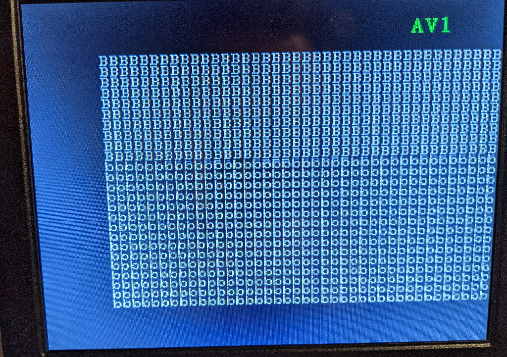
I decided to pull some chips to see what was going on. I decided to remove RAM, the two PIAs and the VIA to see what the test code produced with just the CPU and video hardware on the board.
Mini PET board minus IO and RAM
Unsurprisingly as expected when there is no RAM I got this screen where the letter is flipping between “B” and “b”, this picture also shows that the screen is pretty hard over on the right hand side of the monitor. It would have been nice to have an option to move the screen offset a bit.
It’s all bad RAM
A quick moan
Some documentation on exactly what the builtin test code is doing would be helpful (the documentation just says it tests the first 1K and video RAM) along with what the wave forms from the video circuit should look like. To be fair to Tynemouth Software this might be a deliberate decision to stop other people cloning the board so I’m prepared to cut them some slack.
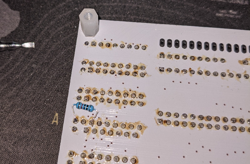
Time to check my handy work
At this point a quick look over the board around the memory decode logic looking for shorted pins seemed like a good idea. I didn’t find much apart from a missing solder joint and a couple of slightly dodgy joints that I fixed with a quick re-flow with a soldering iron.
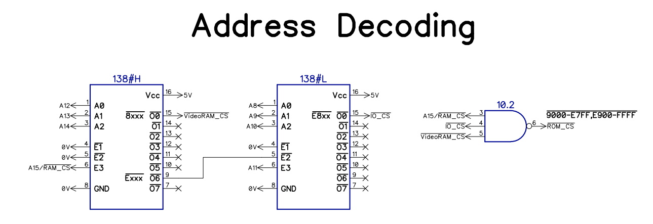
Memory decode schematic
Oh and this bent pin on a chip which was a fairly simple fix.
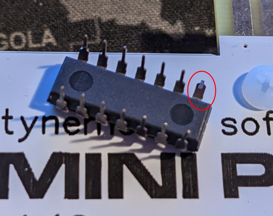
Bent pin on a 74LS07
Time to debug
The next thing I tried was putting the RAM back in and as expected the memory test code ran fine, putting back PIA #2 into the board produced this screen:
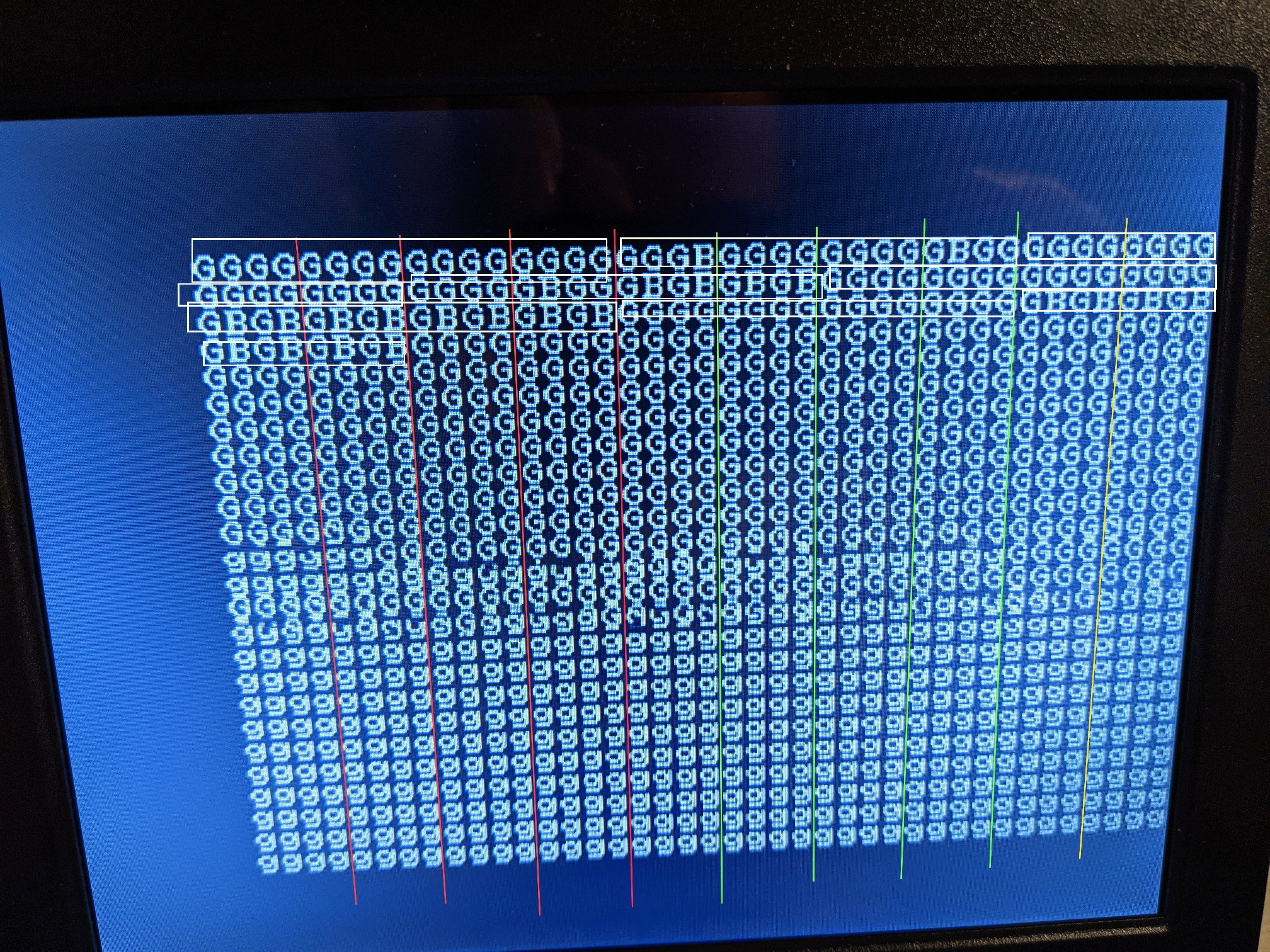
Bad bits in the first 1K
Now in the picture above I’ve drawn vertical lines every four bytes and drawn boxes around each 16 bytes on screen and turned the results into a table
| A3 | 0000 |
0000 |
1111 |
1111 |
|||
|---|---|---|---|---|---|---|---|
| A2 | 0000 |
1111 |
0000 |
1111 |
|||
| A1 | 0011 |
0011 |
0011 |
0011 |
|||
| A0 | 0101 |
0101 |
0101 |
0101 |
|||
| A6 | A5 | A4 | 0123 |
4567 |
89AB |
CDEF |
|
0 |
0 |
0 |
0x | GGGG |
GGGG |
GGGG |
GGGG |
0 |
0 |
1 |
1x | GGGB |
GGGG |
GGGG |
GBGG |
0 |
1 |
0 |
2x | GGGG |
GGGG |
GGGG |
GGGG |
0 |
1 |
1 |
3x | GGGG |
GBGB |
GBGB |
GBGB |
1 |
0 |
0 |
4x | GGGG |
GGGG |
GGGG |
GGGG |
1 |
0 |
1 |
5x | GBGB |
GBGB |
GBGB |
GBGB |
1 |
1 |
0 |
6x | GGGG |
GGGG |
GGGG |
GGGG |
1 |
1 |
1 |
7x | GBGB |
GBGB |
GBGB |
GBGB |
Which strongly suggests that I̅O̅C̅S̅ isn’t quite working correctly when the A4 line is high, which make sense as CS1 on PIA #2 is address line A4
At this point I decided to get out a little toy I’d bought the LHT00SU1 logic analyzer which is a clone of the now unavailable USBee AX Pro 8 channel logic analyzer with a one channel oscilloscope sampling at 12MHz for analogue and 24MHz for digital. These clones are available online quite widely for under £10 for digital only online and around £30 if you want the oscilloscope option, now for software you can use sigrok Pulseview which works but it doesn’t seem to offer a 12MHz sample rate and I found the original USBee AX software worked better for me. Now this software can be found online with a bit of work, so I downloaded a copy to try out, the USBee folks offer the option to buy a hobbyist license for $39 so I have bought1 a copy. I have a non-storage HP 100Mhz ‘scope so this little cheap box together with the HP should let me debug most retro computing systems given the typical clock speeds I care about and higher speed ‘scopes are expensive.
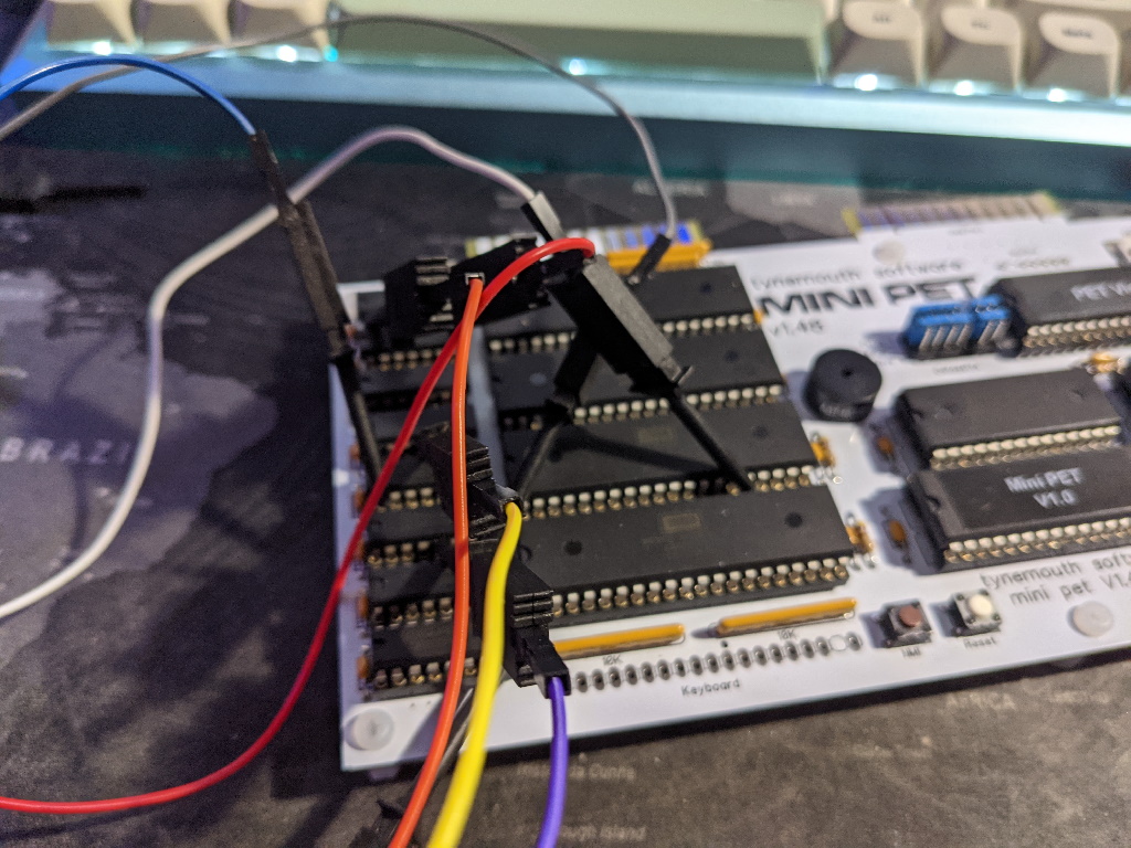
Logic Analyzer attached to board
In the picture above I’ve attached mostly to the address decode logic with one probe for the R̅E̅S̅E̅T̅ signal (used as a trigger) and one for the PHI2 clock on the PIA
Analysing IOCS
Now these signals don’t actually make much sense, so at this point I removed the 74HC138 and tied off the I̅O̅C̅S̅ pin (15) to the 5V line and checked the board, the RAM test now passed so I got a little suspicious of the I̅O̅C̅S̅ signal on the board and thought there might be a short somewhere on the board.
Pull up resistor
To help I put a 10K pull up resistor on the bottom of the board to 5V and bent pin 15 of the 74HC138 up out of the socket so I could check the output without having a short, the pull up should make sure that if I̅O̅C̅S̅ isn’t being driven it will normally be disabled.

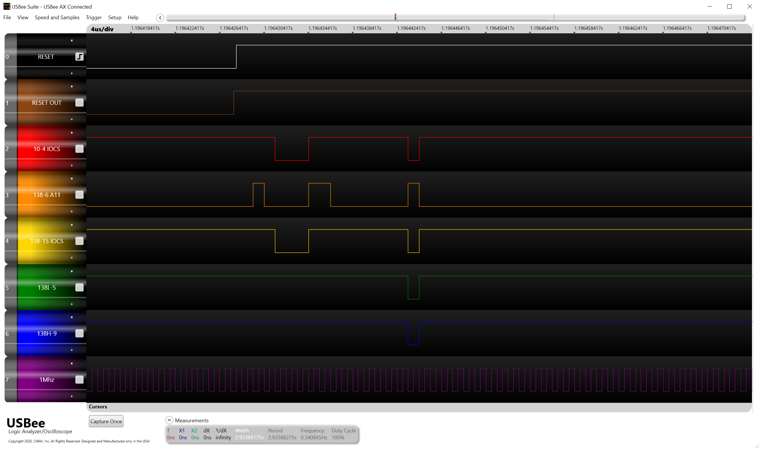
Bad signals
So this shows the next stage along where I̅O̅C̅S̅ is solidly high at the output of our ‘138 but when probed at the PIA input is the same as A15 (I also have enabled the oscilloscope input here with the clock signal)
At this point I decided to have a bit of a closer look at the pins around the 74HC10 that is doing the decode and spotted something I should have seen earlier.
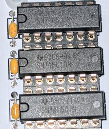
Mixed up 74LS07 and 74HC10
In the picture above you can probably see the root cause of all of my issues, instead of three 74LS07 parts in a nice row there is a 74HC10 in the middle. I probably should have checked this earlier (and I’ve no idea how this happened). So after a quick swap of the chips around and a change of some DIP switches back from the test ROM I got to see this wonderful screen.
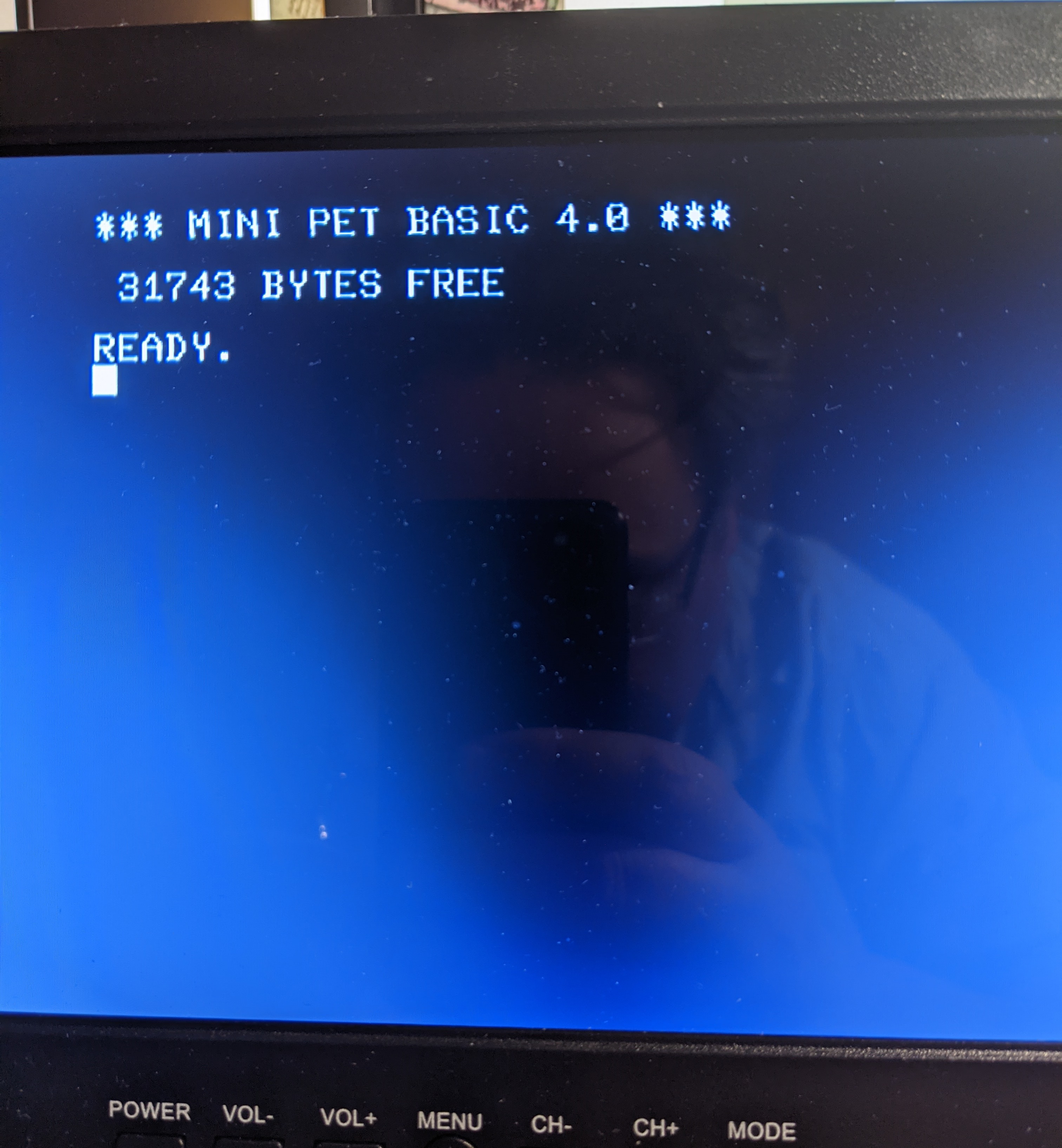
PET screen showing READY
Phew!
Final stages
So once that was all done, I gave the board a quick clean to get rid of the solder flux.
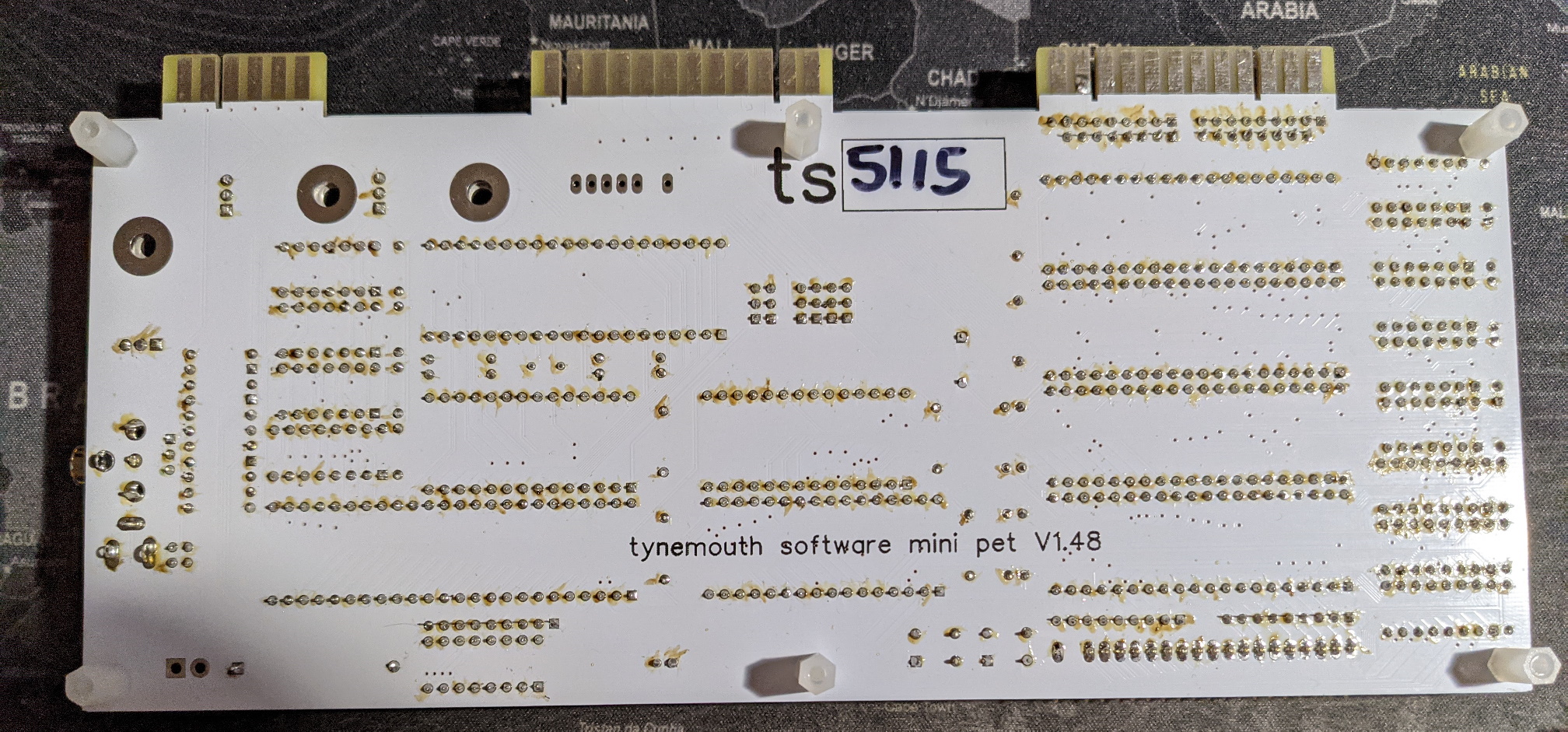
Nasty flux
I have a somewhat elderly can of Servisol De-flux 160 which I used on the boards to get rid of the flux (sadly it also cleaned off the serial number on the board)
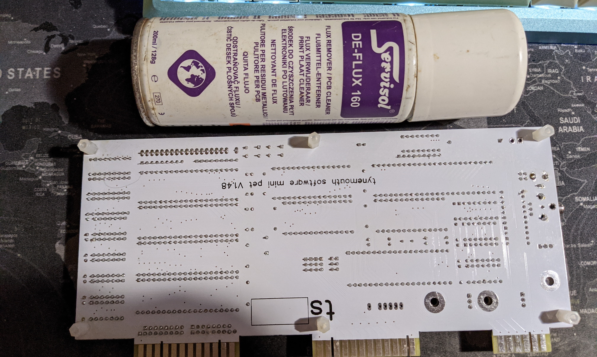
Board clean
Now the boards look a lot better. Next step is to cut out the key caps and put them into clear key tops.
Key caps
Final thoughts
Well now that is all done it’s time to plug in the SD2PET and load some software.
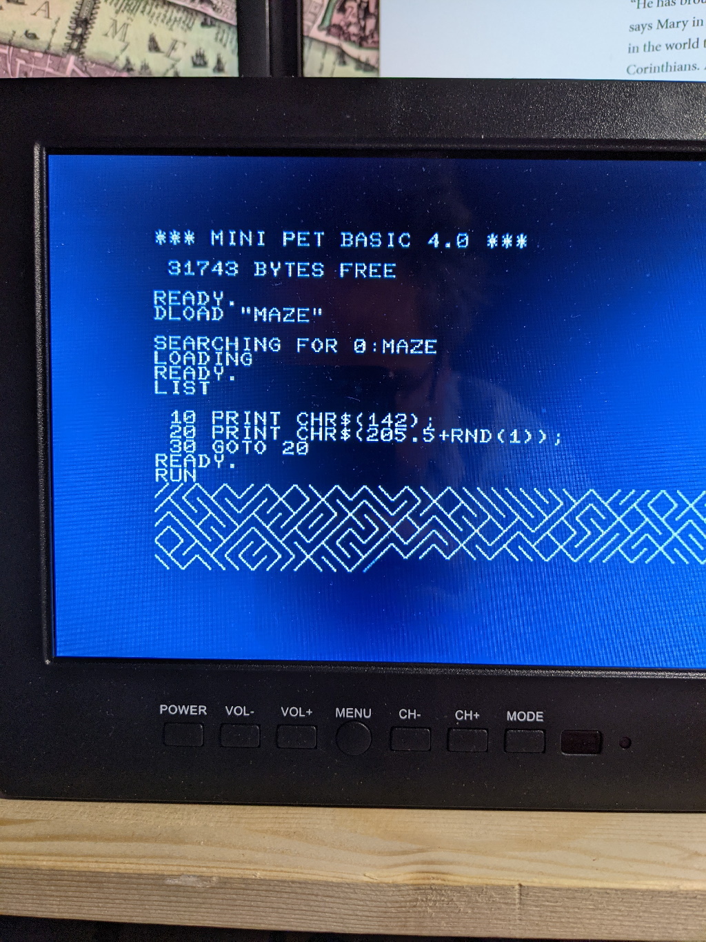
Mini PET running Maze
Here is a shot of the PET running Invaders showing the chiclet keyboard.
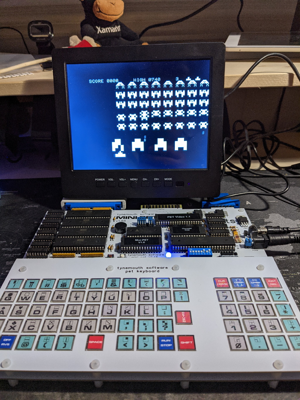
Mini PET running Invaders
Now I suspect this game was the first computer game I ever played (although maybe it was Star Trek), I remember going round to a friends house whose dad had a PET at home and wondering if we could ever hookup the audio output to get some sound as shown in a PETSCI art circuit diagram on the first screen of the invaders game, thankfully the mini PET already has the speaker wired up to the right lines…
So while I have a few small suggestions for the manual and some more documentation on what the test ROM is doing would be nice, I can recommend the mini PET if you have some electronics experience but it’s probably a bit too much for an electronics beginner.
I’m pleased with kit so I’ve ordered a Minstrel 3 (a ZX81 clone with a ZXpand) and a Minstrel 4 (Jupiter Ace clone) to fill out my retro computer collection (I do have an original ZX81 somewhere).
So I’m going to give this kit 5 stars ⭐⭐⭐⭐⭐
-
Since I earn my living by selling software in general I like to have a proper license for software on my computer where I can, retro software is a bit trickier so I cut myself some slack there. ↩