STM8L Discovery board video timing
Next up how we can get the stm8 discovery board to actually generate some video. I’m not going to repeat too much on the theory of how video works I’ve put a collection of links1 at the end of the article I would suggest reading these. In particular the batsocks page which has loads of detail and helped me get my head around things. Initially we’re going to use a super cheap two resistor, two diode voltage divider to generate our video along with the stm8.
The full gory specification for how monochrome video works is contained in ITU-R BT.470-5 Thankfully this stops around page 9 where it heads into details for colour.
Code for this discussion is here on github
So the basic video circuit that I’ve used for testing uses a couple of resistors and diodes. I’ve used a potentiometer in the sync circuit to allow me to adjust the voltage levels. Measuring the resistors I’ve used gives 462Ω for the video signal and 806Ω for the sync signal.
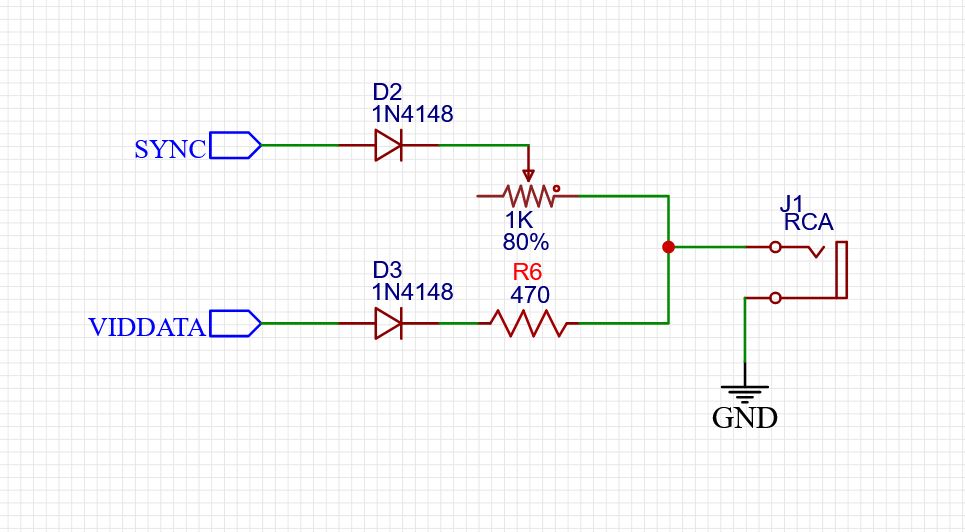
Twin diode resistor circuit
These are wired up to a couple of pins on the STM8L so when both pins are at VCC we get a voltage of 0.671V for the white level and a when the video data pin is ground either 0V or 0.244V (This is actually incorrect as there will also be voltage drops across the diodes)
Sync is at 3.3V for the data portion, there is also a resistor in the display to give a 75Ω impedance so the whole thing forms a voltage divider.
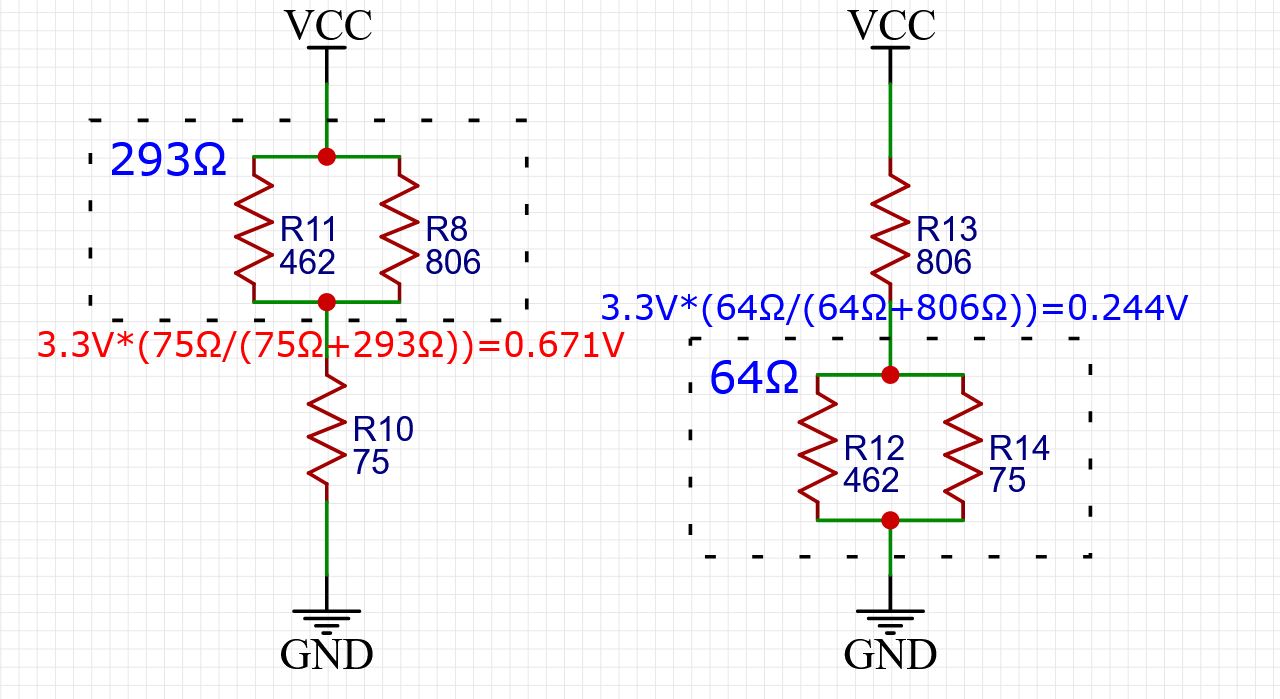
Effective circuit
This circuit has some issues with the small 9” display I’ve been using for testing. When the ground signal is connected to the Discovery board the SWIM debug port sometimes latches up. I’m not entirely sure why, but I have a buffered transistor version of the circuit which I will try instead to see if it helps. I would recommend trying it out to see it works for you with your monitor, my values are purely experimental.
Video sync timing
So the basic line of PAL video is 64uS wide which maps nicely to 1024 cycles of the STM8L 16Mhz system clock. For the pulses at the start of video frame we need to put out either a short (2.35uS) or wide pulse (27.30uS) every 32uS. In order to achieve this we use the STM8L timer 1 with a period of 512 cycles and setup in PWM mode.
For a regular video line comparator 1 (CCR1) is used to generate the sync line, this goes low initially as the comparator is set to 75 (4.7uS), for the second half of the cycle we set the comparator to 0 so for the the second cycle the sync line is kept high all the way through.
We start to output data at counter 219 which gives a decent gap for the front and rear porch of the video timing.
So to help our processor along we mostly use DMA to keep the timer in sync with everything. We setup CCR2 to have a value of 128 and DMA3 to work it’s way along a table of sync values, so on cycle 128 DMA3 reads a value from the ROM and writes it into the CCR1 pre-load register so when timer 1 reaches its 512 clock cycle end the new value is written into CCR1.
Sadly DMA3 (which is the only DMA channel that can use the ROM as a source) has a byte wide counter, so we also setup a interrupt routine that every 128 video lines when DMA3 runs out of data, sets the DMA up for the next section wrapping it after all 625*2 data values have been written to the CCR1.
In the code this is in the DMAChannel23Int routine.
Finally we use the sync signal as an input to timer counter 3 which we use as a line counter.
Video data timing
So we’d like to output some video data. For this we use the SPI port clocking the data out at 8Mhz.
To write our data we get DMA channel 2 to write data from one of two buffers into the SPI data register, we render the next line while the DMA system is sending the previous lines data out of the SPI port.
To start the DMA channel writing data we setup DMA channel 0 to enable the SPI on cycle 219 of video data by writing to SPI1_ICR. Since this can only come from RAM we have a single byte which contains the value required to enable the DMA. In the second half of our line we write the value again, but this doesn’t matter as we just setting it to the same value.
We don’t want to have the SPI running all the time so we use timer 3 which counts sync pulses, setup two comparators (odd and even frames) which a comparator interrupt fires we start to generate our line data (racing the video beam).
The demo code on github simply puts solid lines at the top and bottom of the screen (see linerender in main.asm) and makes the first and last bytes of data to be a zero so the data line is a 0 when no data is being clocked out.
When Timer 3 fires, the first thing we do is to setup the DMA1 channel (which writes to the SPI) and disable the SPI TX DMA, this gets enabled by DMA channel 2 firing when timer 1 comparator enables the DMA1 by writing to SPI1_ICR.
We then sit in a loop rendering a line into one line buffer while the DMA writes the other line buffer out. We then read the timer 3 counter until we have rendered 200 lines (25*8) at which point we turn the off DMA and toggle an LED to give a bit of confidence.
This means our main code can run in the gaps between the line render interrupt running. The DMA3 interrupt has a higher priority than the timer 3 interrupt so our sync pulse counter can be updated.
Video Jitter
The code as it currently is in the repository on github uses an external clock on the OSC_IN pin (PA2), the reason is to avoid jitter on the clock edges. There is macro definition of EXT_CLOCK defined in constants.inc to control this (otherwise we use the internal 16Mhz clock)
Why do this? Well if you use the internal oscillator there is some jitter in the edges which means the video looks like this:
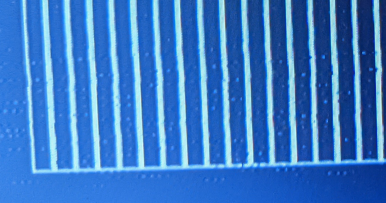
Lines jittering on screen
You can see the lines aren’t very straight. Since my oscilloscope has a wave form generator I set that up to output a 16Mhz signal and ran that into the STM8L PA2 input. The video now looks much better:
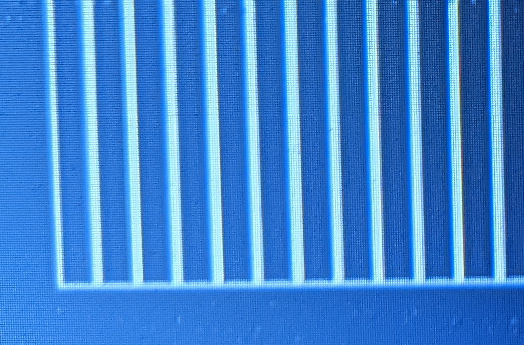
Straight lines on screen
There is some sparkling which I think is the backlight circuit in the 9” monitor (I’m hoping adding a transistor as buffer stops this) which don’t show up with a my original Sony CRT TV.
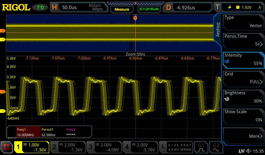
Clock output jitter
If you uncomment the lines at 59-66 in boardsetup.asm you can output the internal clock (or the external clock) on PC4 by raising the persistance on my oscilloscope you can see how the internal clock to the STM8L has very jittery edges.
;Output the CCO on PC4
	bset PC_DDR,#4
	bset PC_CR1,#4
	bset PC_CR2,#4
; Line below puts HSI out on PC4
;	mov CLK_CCOR,#%00000010
; Line below puts HSE out on PC4
	mov CLK_CCOR,#%00001000
One final gotcha
When I was debugging this I found it somewhat difficult to make sense of triggering the timers. One important thing is that the counters need loading by setting bit 0 of their EGR registers which makes the preload counters copy into the main registers.
In the next post I discuss adding characters and sprites to the code.
Links
- https://www.batsocks.co.uk/readme/video_timing.htm
- http://martin.hinner.info/vga/pal.html
- http://blog.retroleum.co.uk/electronics-articles/pal-tv-timing-and-voltages/
- https://circuitcellar.com/research-design-hub/build-a-composite-video-text-terminal/
- https://www.avrfreaks.net/forum/simple-composite-video-output