Keyboard build - Part one - Testing the PCB
Please note, I’m no expert (but I know which end of a soldering iron is hot), this is my first keyboard build, this is more of a build log not a set of instructions so treat my advice with caution. The images are usually bigger so a right click and view image will show the larger version.
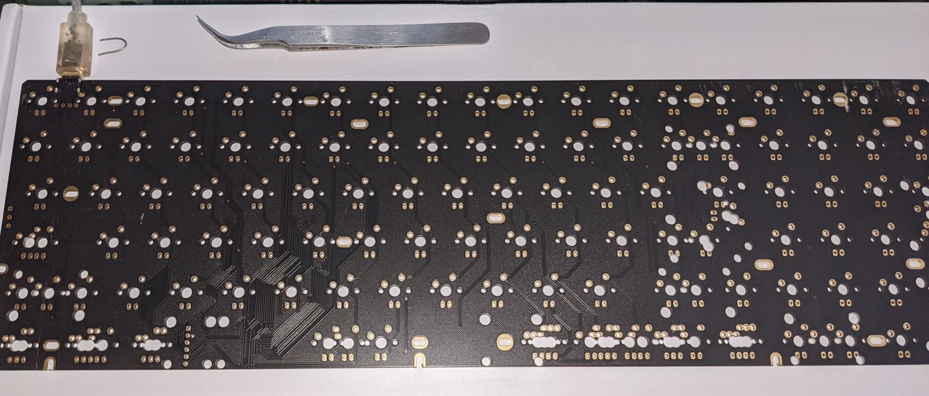
So before we start doing anything with our new keyboard we need to test the PCB to see if there is anything wrong such as a resistor or a diode being knocked off the PCB before we start soldering. While you can skip this step in theory, doing so could cause a load of pain later on.
So connect the PCB up and grab some tweezers and possibly a little loop of wire (so you can press the FN key at the same time). I’m going to use KeyboardTester.com which shows which keys have been pressed which saves a bit of time. Since I happen to be a programmer I’m also going to use a small WPF application that basically displays the down key messages from Windows, which allows us to distinguish between left and right key codes for things like shift keys.
Testing the PCB
So one issue is the default melody 96 layout doesn’t have the right hand menu or ctrl keys mapped. The default layout can be found in the QMK repository
But I’ve got some screen grabs here for you to look at.
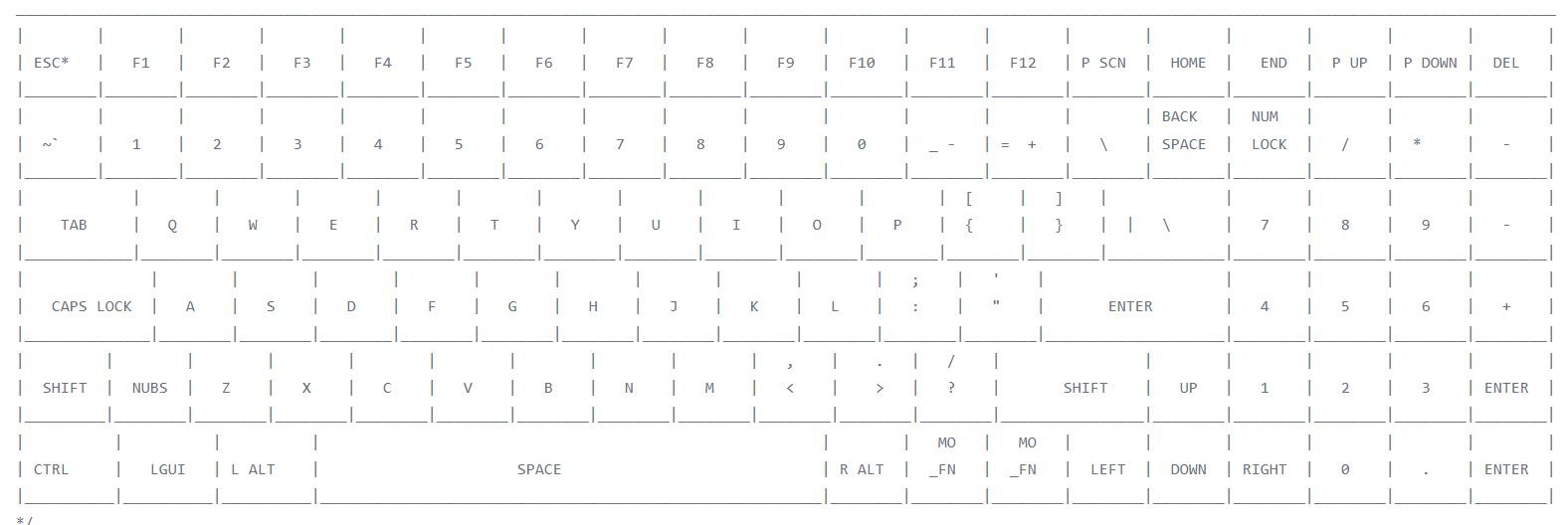
Main keys
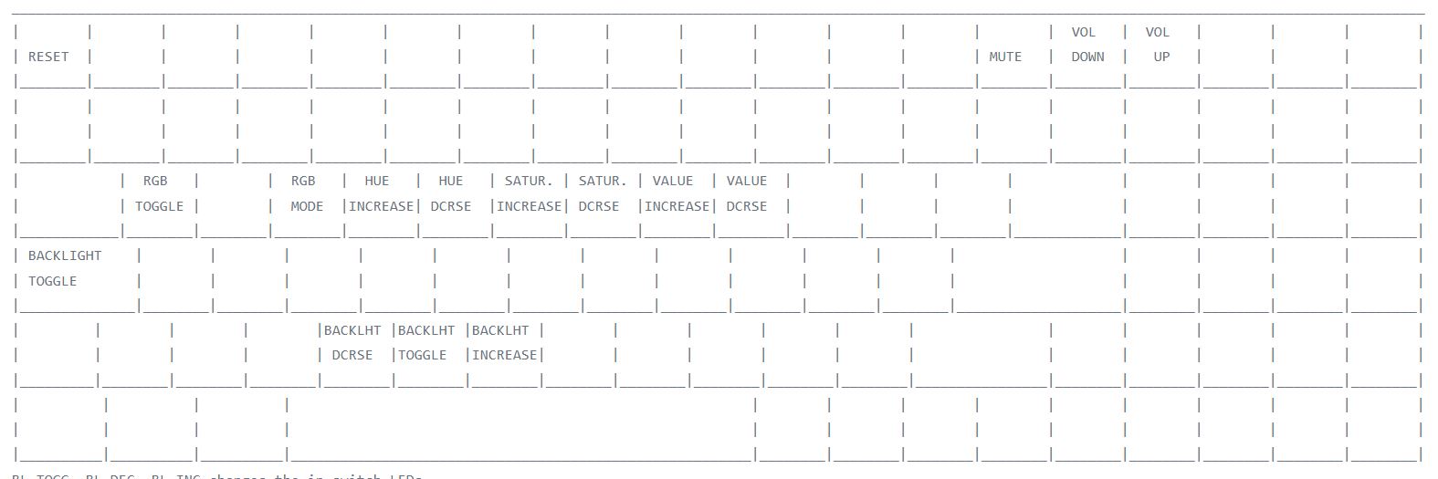
Function keys
So one thing we can do is test the left and down positions and by using the wire loop in the MO_FN key switch position and tapping Q with the tweezers we can check the ARGB lights work, if we move over and toggle the E key we can cycle through the RGB modes.
We could in theory alter the layout at this stage to match my desired one and reprogram the keyboard but I think I’m going to leave that until a bit later.