Keyboard build - Part two - Fitting the stabilizers
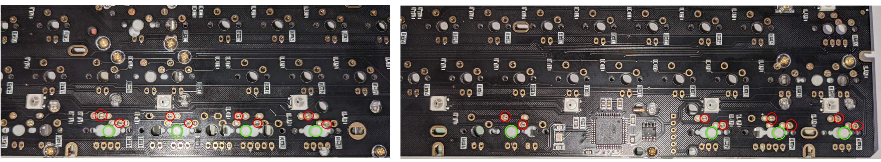
So for my chosen layout (see this previous entry) I need to add the PCB mounted stabilizers for all the keys two key cap units and wider (It’s easy to tell they have multiple crosses in the under side of the key caps), I have circled them below in this layout picture.
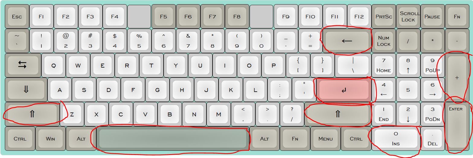
Stabilizer positions
The Melody 96 kit I have bought comes with two packets of stabilizers (gives some spare) that clip into the PCB. I bought an upgraded set of stabilizers that actively screw into the PCB, these have come pre-lubed (You can see the lube on them which I’ve tried to photograph). There are also stabilizers available that can be attached to a plate instead.
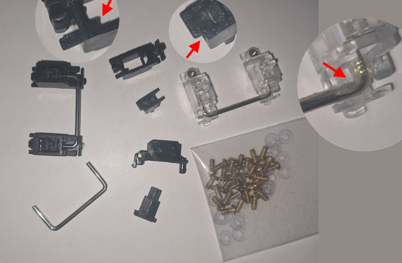
Stabilizer parts and styles
The picture shows the parts that go to make up the stabilizer, basically you slot the parts together putting the cross towards the top, then push the wire into the stabilizer and clip it into body. The body and post have a matching notched slot and tab, you probably should lube these with some sort of silicon grease, clip them and do various other things before you fit them.
The stabilizers clip in with the hooked end through the bigger hole and the screw end through the smaller one, screws and a washer are then screwed in from the other side of the PCB. The photo below shows the last stabilizer about to be screwed in and as you can see there are plenty of spare screws and washers in the upgraded stabilizer packet. I used a phillips #1 screwdriver for this as it seemed to be the best fit.
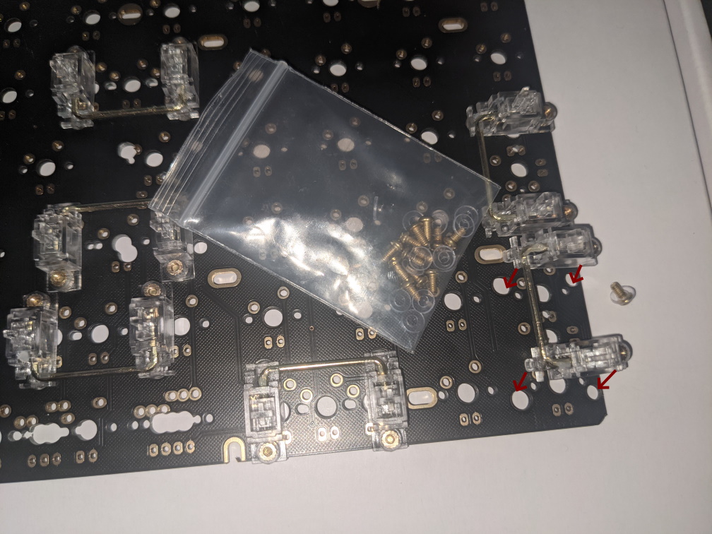
About to mount the last stabilizer
When we build the keyboard, components that are attached to the top of the PCB need to be installed first because after the plate is attached and the switches are soldered in we will have limited access to the PCB without de-soldering the switches.
The Melody PCB allows stabilizers in several positions to support different layouts (around the space bar / enter key) so a test fitting is in order to make sure that the stabilizers clip into the key caps correctly. It also gives me a chance to test fit the switches into the PCB in the bottom row to make sure that I’m using the right switch position for the key caps.
WARNING: When removing the key caps a couple of the stabilizer bars popped out, easy enough to refit but check they’re securely seated.
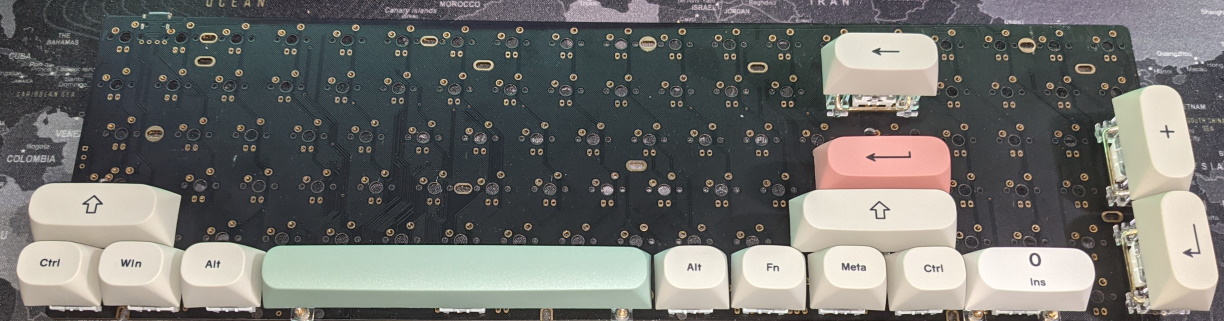
Test fitting the key caps
I’ve turned over the keyboard and taken photos of the bottom from where I’m going to be soldering to make sure I know exactly where things should be, I have also taken a bunch of photos of both sides of the boards without switches in case I need follow a PCB trace later on.
Underside of PCB