Keyboard build - Part three - Plate spacers and switches
The plate is the backbone of most keyboard designs, if you’re doing your own layout often you don’t even have a PCB the switches are inserted into the plate and wired up directly (see Reddit keyboard building guide for more details)
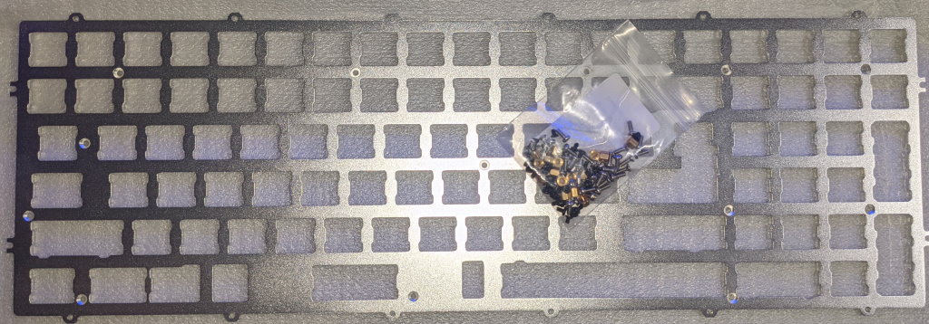
Plate and screw bag
Now if you’ve bought the Melody 96 with a hot swap PCB so you don’t have to solder switches in then you will definitely want to install the spacers that are in the bag, otherwise the only thing holding the PCB in the case will be the friction of the switches in the sockets. There is QR code on the screw bag that links to a document that talks about the screw types and suggests installing 3-6 spacers (I have no idea there is a different QR code for the hot swap sockets PCB so check in case the instructions are different.)
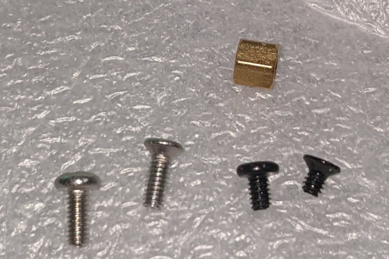
Screw types and spacer
The bag contains four different screw types and some brass spacers, the various screws are used as follows:
- Small countersunk black screw, plate to spacer.
- Small round head black screw, PCB to spacer.
- Long countersunk silver screw, case top to bottom.
- Long round head silver screw, mounts plate and PCB to case top.
So the question is how many of the spacers do I use for my bare PCB? I have decided to add the spacers in the all of holes in the top plate using the countersunk black screws, in spite of the instructions. The advice I’ve seen online suggests there isn’t a need if you’re soldering the switches into the PCB but I feel the extra stability might be useful and doing it afterwards will mean a lot of desoldering.
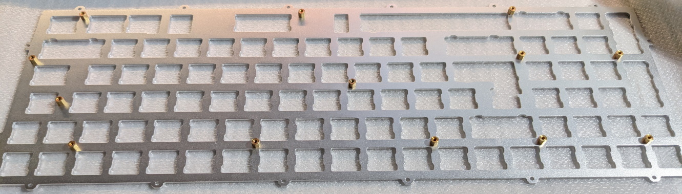
Plate with spacers
Next step is to screw the spacers into the PCB with the round head screws from the underside of the PCB, then I’ve fitted a couple of switches in the middle of the board and switches around the edge of the board. I used a phillips #0 screwdriver and a 4.0mm nut driver.
Note I over tightened one of the plate to spacer screws and it sheared off, not a problem as there are spares but something to be aware of.
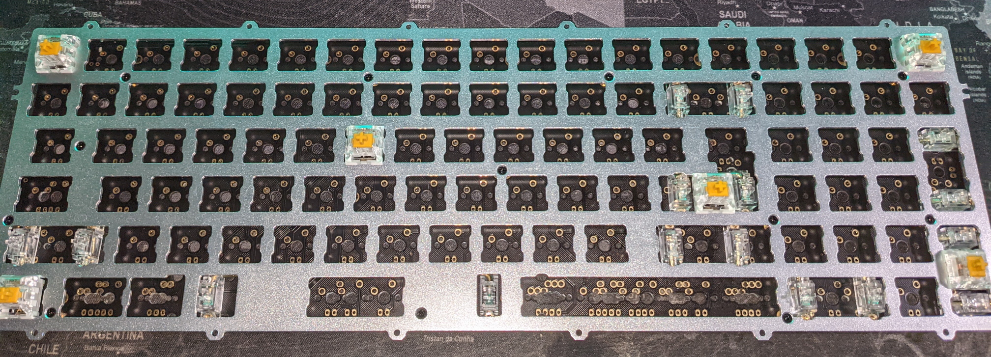
Switches around the corners and middle
Remember to unplug the keyboard before soldering.
I then soldered these into position and then tightened up the screws attaching the PCB the spacers, before populating the rest of the switch positions and getting busy with the soldering iron. In this photo I haven’t done the “\ |” key as the switch can twist a bit due to the plate supporting both ISO and ANSI style enter keys, so I’m going to wait until I have the key caps on around it to help keep it straight (turns out I soldered it carefully before doing the key caps). The other switch that’s missing is the caps lock as there are two positions on the PCB and I need to find the key cap in the bag so I can check the alignment.
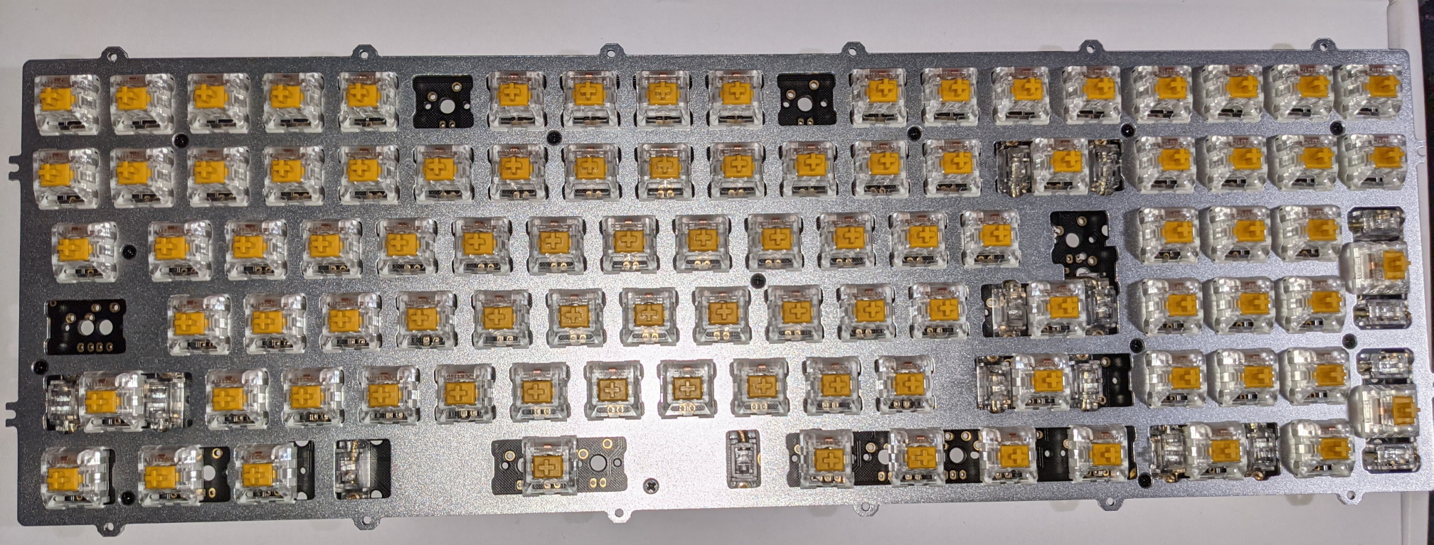
Nearly all the switches soldered
As I’ve been soldering every 20-30 switches I’ve done quick switch test and see if everything works, but since I haven’t updated the firmware with the right switch mapping not everything will match up (two thirds of the function keys are out of their normal position).
Remember to unplug the keyboard before soldering.
For me I’ve used lead free solder and it took a shade over an hour to solder the switches into position.