STM8L Discovery board getting started
The WPF Invader code is now in a pretty good place so it seemed like a good time to get started on the STM8L Discovery board and see if I can actually get something up and running on this board.
The board comes with a LCD panel, a means of measuring current draw, a switch and two LEDs. Now I’ve never programmed an STM8 family part so I thought I’d get started by writing a quick LED flasher program.
Install the software
First we need to install the development environment, in my case I’ve decided to go with ST Visual develop IDE for developing ST7 and STM8 applications and write assembler directly rather than use a C compiler.
The core of the IDE is a bit elderly (but seems to be updated recently some of the include files have dates in the 2017 range) it likes to run as an administrator, other wise you get a permission denied error.
I ran into an issue where the software when I tried to debug gave an error “STVD Connection error (usb://usb): gdi-error 40201: can’t access configuration database” a quick google later I found this fix which suggests uses regsvr32 to re-register DAO350.DLL.
Regsvr32 /u "C:\Program Files (x86)\Common Files\Microsoft Shared\DAO\DAO350.DLL"
Regsvr32  "C:\Program Files (x86)\Common Files\Microsoft Shared\DAO\DAO350.DLL"
Getting started
Select File / New workspace then create Workspace
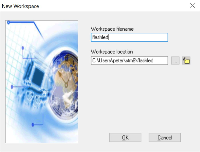
Create workspace dialog
Followed by the create project dialog, selecting the ST Assembler Linker tool chain
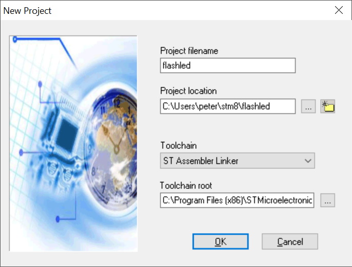
Create project dialog
Then finally the select MCU dialog in our case we want the STM8L152C6
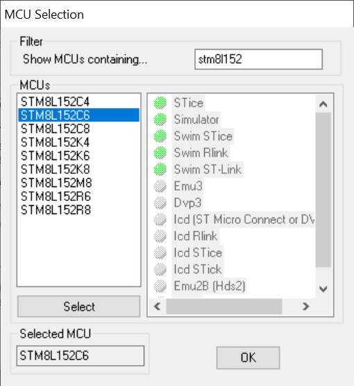
Select MCU dialog
This creates a blank project with pre built mapping file for the linker and a main assembly file which clears the ram and sets up the stack.
Annoyingly what it doesn’t do is automatically add the file which contains the register definitions for the STM8L152C6. You can manually add this to the project using the “Insert Files into Project” under the Project menu then adding the file C:\Program Files (x86)\STMicroelectronics\st_toolset\asm\include\STM8L152C6.asm which defines a bunch of public symbols.
At this point I’ve removed the LCD from the board as I don’t want to damage it by mis-configuring the GPIO pins.
To use the symbols add #include "stm8l152c6.inc" to the top of main.asm which brings a bunch of extern variables to match our definitions created by the STM8L152C6.ASM file.
Flashing the LEDs
For our first project we’ll do something simple and flash a couple of LEDs. On this particular discovery board the LEDs are connected to ground with a current limiting resistor and attached to gpio pins C7 & E7.
First thing to do is add the MCU files as above, in this screen shot I’ve made the IDE display the full paths to the files so you can see where the register definitions come from.
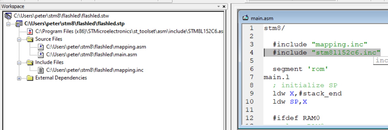
Initial code in IDE
So lets add a call to routine to initialise the gpio:
; Setup the gpio stuff
  call init_gpio
infinite_loop.l
  jra infinite_loop
Then we can add a routine to actually setup the gpio:
;
; Setup up the gpio ports
;
init_gpio
; set everything to have a pullup resistor in input mode
  mov PA_CR1,#$FF
  mov PB_CR1,#$FF
  mov PC_CR1,#$FF
  mov PD_CR1,#$FF
  mov PE_CR1,#$FF
  mov PA_CR2,#$00
  mov PB_CR2,#$00
  mov PC_CR2,#$00
  mov PD_CR2,#$00
  mov PE_CR2,#$00
  mov PA_DDR,#$00
  mov PB_DDR,#$00
  mov PC_DDR,#$00
  mov PD_DDR,#$00
  mov PE_DDR,#$00
; setup for LEDs
  bset PE_DDR,#7
  bset PE_CR1,#7
  bset PC_DDR,#7
  bset PC_CR1,#7
  ret
The first chunk of this code simply sets all of the GPIO pins to be inputs with a pull up resistor, the final lines setup the two ports that have the LEDs attached to be outputs in a push pull configuration. This is done by setting the data direction register (DDR) bit 7 to true and the control register 1 (CR1) bit 7 to true, there is no need to set CR2 as we don’t care about the output speed in this case.
We’ll need a delay routine, so as a temporary hack lets just load up one of the 16 bit index registers and count down in a loop.
delay
  ldw X,#$FFFF
loop_delay
  nop
  decw X
  jrne loop_delay
  ret
Finally lets actually flash some LEDs by modifying the infinite loop.
infinite_loop.l
; Turn on green and blue LEDs
  bset PE_ODR,#7
  bset PC_ODR,#7
  call delay
; turn green off, blue on
  bres PE_ODR,#7
  bset PC_ODR,#7
  call delay
; turn green on, blue off
  bset PE_ODR,#7
  bres PC_ODR,#7
  call delay
; turn green off, blue off
  bres PE_ODR,#7
  bres PC_ODR,#7
  call delay
  jra infinite_loop
Now we can start to debug. If you set the Debug instrument / set target menu option to be the simulator then you can watch the ODR registers. Once you’ve started to debug you can select the plotter via the “Debug instrument” I then added both of the PC_ODR & PE_ORD registers to the plotter:
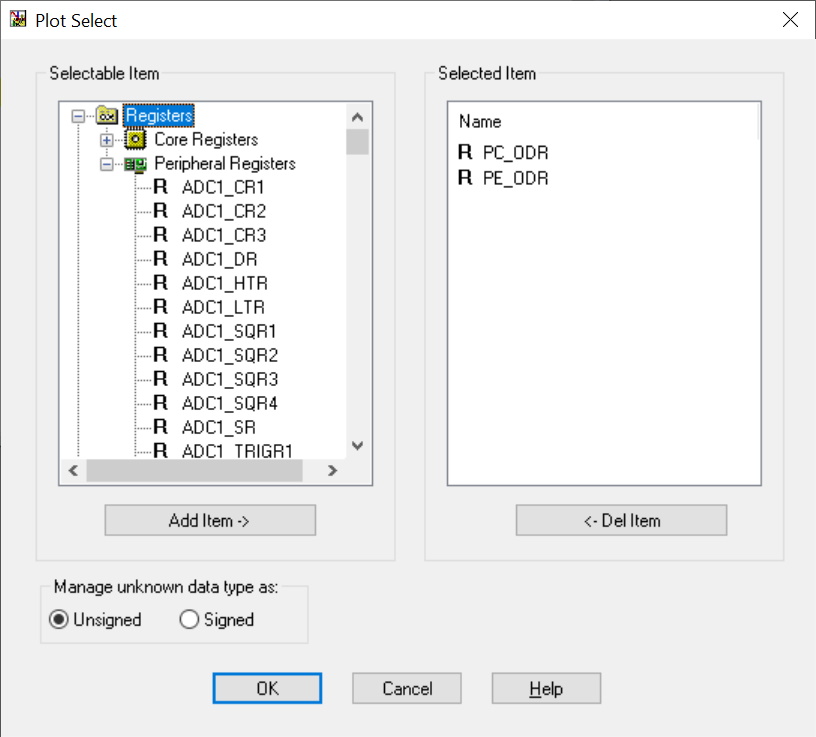
Plot select
I then put a break point at the loop and debugged the main loop a few times. Displaying the plotter window by selecting view / plotter and selecting tools / zoom / zoom fit to window lets me see the output data being toggled.
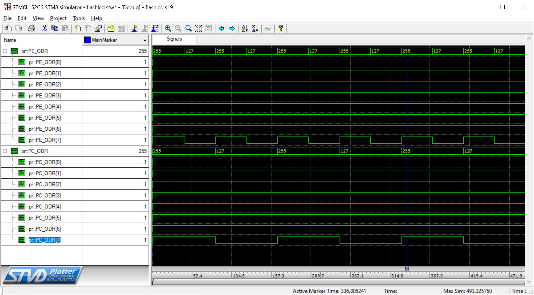
Signals toggling
The final stage is to change the target to our board (by selecting the SWIM ST-link) and run the code on the board. You can examine the peripherals and registers by selecting them from the view menu and add break points.
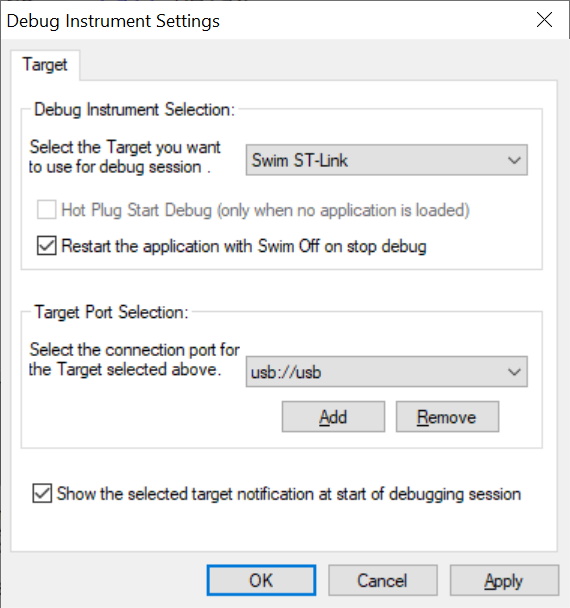
Change target
Hopefully by this point you actually have some flashing LEDs on the board (please excuse the image quality).
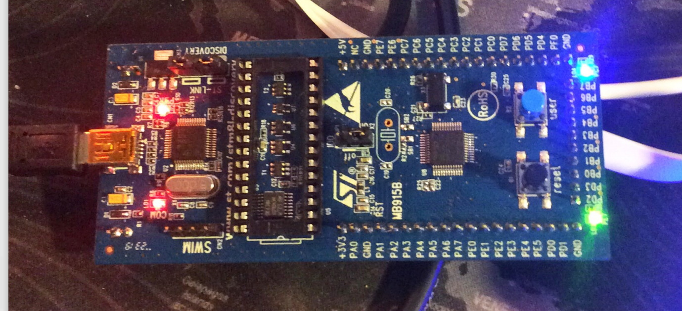
board with both leds on