Keyboard build - Part five - LEDs and some mistakes
So before fitting the key caps I want to solder the under key illumination onto the keyboard, I’m not sure it goes well with the key caps I’ve chosen but it does leave open the option to change to a key caps with a front illuminated legend in future and I don’t have to turn it on.
Soldering the LEDs
To turn on the LEDs you need to press either FN+CAPS or FN+V as you can see from the picture below of the default map for the melody 96. You may also want to push FN+B to increase the brightness before we do some testing.
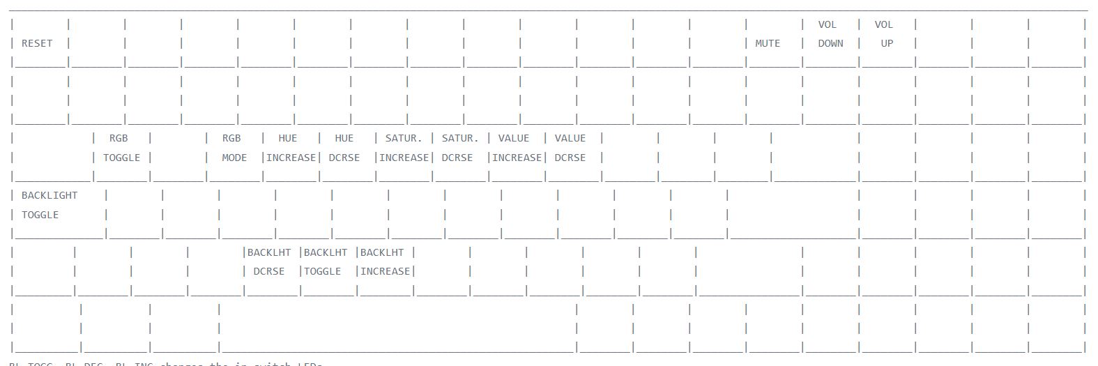
Function keys
It’s worth checking the LEDs work and are the expected way around (long leg is the positive anode pin) I would recommend with another keyboard plugged in at the same time pressing caps lock which will turn on the LED for caps lock. I took an LED and touched it on the underside of the PCB where the caps lock key switch is with the long leg in the hole with the little “+” and the shorter leg in the other hole. I then moved on to another pair of LED holes to check that the back light is working (assuming you’ve turned it on).
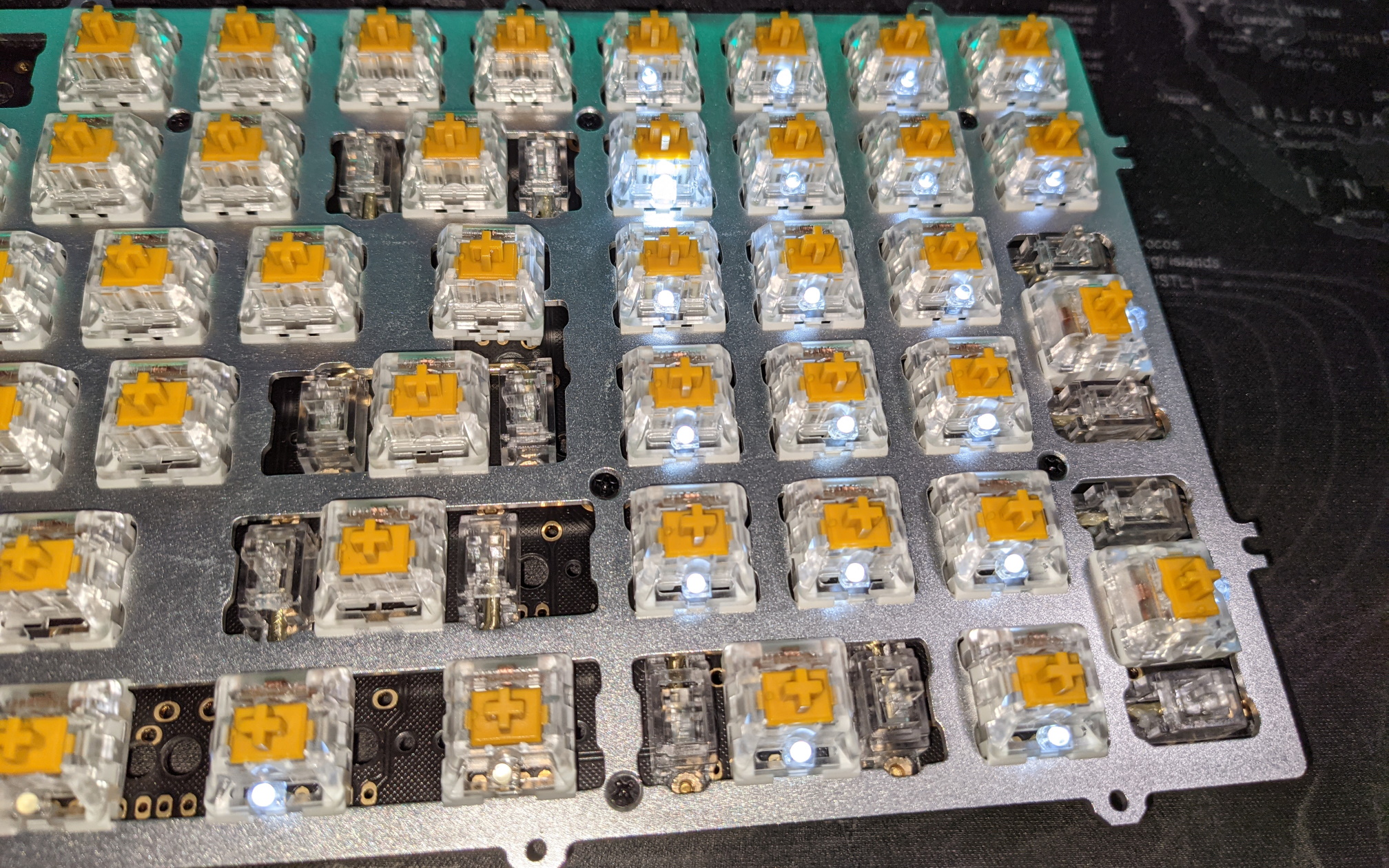
LEDs showing num lock turned on
The num lock LED toggles when num lock is pressed doesn’t have it’s brightness controlled by the firmware so will always be at full brightness like caps lock (you should be able to see this in the picture) so like caps lock makes a good key to check your LEDs.
I have used white 1.8mm LEDs in this build, larger ones may foul when the key caps are added.
You can also in this picture that I have messed up the Fn key LED and used the wrong holes, I also have a solder bridge on the right ctrl key which is why it isn’t lit. You should check before inserting the LEDs all along the modifier key row as it’s tricky to see exactly which holes are the correct ones in this area.
Remember to unplug the keyboard before soldering.
When soldering the LEDs I’ve found that doing a row at a time feels best to me, I insert the LED and make sure it is tight up against the key cap housing then bend one leg on the underside of the board to keep it in position. Once I’ve inserted the LEDs for a row I turn the board over and solder just one leg. Once I’ve done that I put the solder down and work my way down the row heating the solder joint up and then pulling the LED by the leg gently (with pliers) so the led is seated firmly. I then turn the board over, check the LEDs still look fitted fixing those that don’t, back to the other side of the board and solder the other leg. Once I’ve done that I plug the key board in and check my handiwork. If everything looks good I then clip off the legs of the LEDs.
Pulling the LEDs gently is important, I broke a couple which meant I had to do some rework. I’m not sure this method is the best one, suggestions are welcome via email, twitter etc.
Remember to unplug the keyboard before soldering or clipping off LED legs.
This is much slower work than the switches I’d guess allow three hours, there are LED sockets that could be used instead, if I was doing this again I’d install them before the stabilizers and switches and then you could also swap led colors if you fancied.
One final note, although the firmware says that scroll lock has an LED after a conversation with YMDK I found out it isn’t wired up (As nobody uses it). If you want to have a scroll lock LED you’ll have to break out the Kynar wire and put a patch in.